It is possible to begin straightaway designing a heat exchanger from smaller diameter copper tubes. These principles can be used to design a drop-in replacement coil for an existing product, where the space constraints are the same; or they can be applied to a completely new design, for example with a change of refrigerant, to meet performance objectives such as heat exchange capacity or airside pressure drop.
Basic design principles have emerged from experience.
Detailed optimization of heat exchangers makes use of complex equations and methods of computational fluid dynamics (CFD) to analyze the airflow around the tubes and fins as well as computer simulations of refrigerant flow and temperatures changes inside the tubes.
Aluminum Micro-Channel Tubes
Optimized AC coils using small diameter copper tubes were compared with aluminum microchannel tubes. The copper tube-fin (T-F) coils were very competitive with respect to heat exchange capacity.
An optimal design can be accomplished using simple design principles. The Copper Alliance refined several useful design principles for coils made with smaller diameter copper tubes. This step-by-step procedure simulates and optimizes every aspect of the heat exchanger design, from tube spacing to fin type to tube circuitry.
Tube Spacing and Fin Design
A methodical approach to the design of heat exchangers using smaller diameter copper tubes is summarized by the following steps. See study: The principle of designing fin-and-tube heat exchanger with smaller tubes.
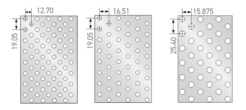
Step 1: Determine the best ratio of transverse tube pitch (Pt) to longitudinal tube pitch (Pl) by fin efficiency analysis. The transverse tube pitch represents the spacing between rows and the longitudinal tube pitch represents the spacing between tubes in one row.
Step 2: Optimize transverse tube pitch and longitudinal tube pitch by analysis of performance and material cost. The tube pitch may be determined in part by the radius of curvature of the hairpin tubes for a given tube diameter.
Step 3: Optimize fin pattern by comparing performances of fins with different patterns through CFD-based simulations (See webpage on Performance Simulations.) Commonly used fin types are louvered, slit, and wavy.
Step 4: Test the performance of the prototype heat exchanger with smaller diameter tubes.
Step 5: Develop empiric equations for predicting performance of heat exchanger with smaller diameter tubes.
Tube Circuitry
Other variables are the number of tubes, the length of the tubes, and the tube circuitry. Design principles relating to tube circuitry are as follows.
- Countercurrent heat transfer between the condenser refrigerant and the outside air is adopted to improve the logarithmic average temperature difference and enhance heat transfer. In other words, if the refrigerant is flowing through the tubes in the rows from left to right then the outside airflow should be from right to left.
- The inlet of the condenser circuit is located higher than the outlet to avoid the adverse effect of gravity on the heat exchanger.
- Entrances of different paths are placed close to each other; exits also are placed close to each other but as far away as possible from entrances. In this manner, losses of heat transfer efficiency from reheating thereby can be avoided.
- The different tube lengths of the path should be kept the same, to ensure uniform heat transfer of different channels.
- Tubes can be parallel on the second half of the condenser circuit to improve overall heat transfer uniformity and meet the comprehensive performance requirements of condenser heat transfer and pressure drop.
These design principles have been described in detail in a separate paper, Design of 5 mm Copper Tube Heat Exchangers for Display Cabinets with R404A from Purdue Conferences: Read more.
Manufacturing Equipment and Processes
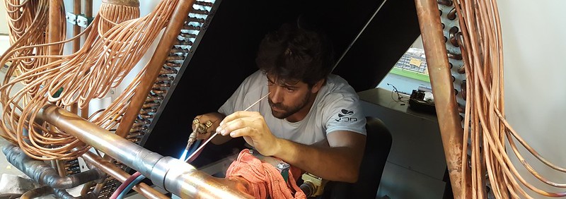
Part of the design process is to ensure that the coils can be manufactured. Versatile equipment for producing a wide range of heat exchanger coils from smaller diameter copper tubes is available now. High-volume production of tube-fin (T-F) coils with smaller diameter copper tubes for residential air-conditioner has been an accomplished fact for more than a decade and the successful production of coils for refrigeration systems and commercial applications is ever broadening.
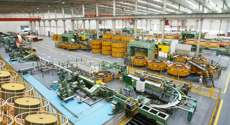
For any manufacturer, a major attraction of T-F coils with smaller diameter copper tubes is the versatility of the production lines. Equipment today is capable of short runs of specialty products as well as high-volume production. Either can be accomplished with speed and precision. Coils for commercial applications typically are not produced in high volumes, so fast-yet-flexible production is paramount.
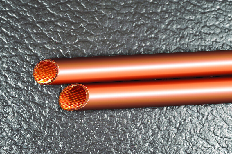
Round copper tubes laced through optimized plate fins are the basis for highly efficient evaporators, condensers and gas coolers for countless applications in refrigeration and air conditioning.
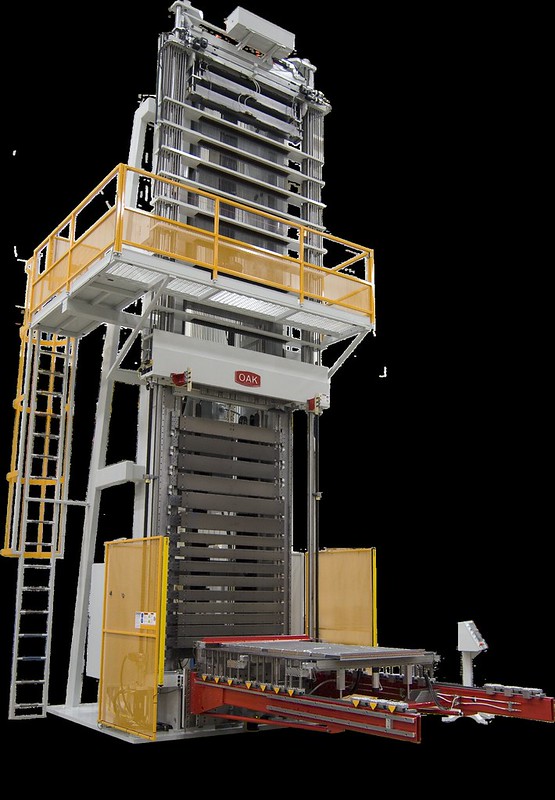
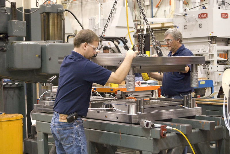
As tubes with smaller diameters became available, equipment and processes that could handle the smaller diameter tubes were developed in tandem. Such tube handling equipment is now widely available for smaller diameter copper tubes. Tube benders, lacers and tube expanders are still at the heart of such production, but the manufacturing equipment had to be adapted to smaller tube diameters. Equipment makers responded quickly and admirably so that a manufacturer can purchase and/or build the equipment necessary to establish a reliable and versatile production line for the manufacturing of coils from smaller diameter copper tubes.
For additional technical support, contact:
Marcus Elmer, Copper Development Association
Additional Resources:
- Presentations: Effective Design of Small Diameter Copper Tube-Fin Heat Exchangers
- Technical papers from conferences
- Webinar: Construction of Small Diameter Copper Tube-Fin Heat Exchangers
- Series: Technical presentations from innovative industry experts who are active in the development of new applications for copper tubes